 Deciding to build the K2 was difficult. On the pro side,
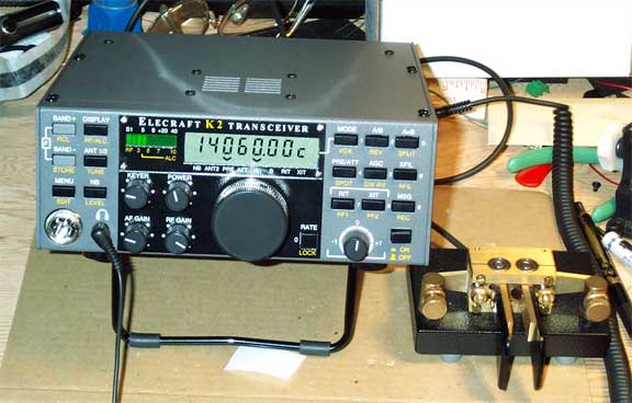
The Elecraft K2 is a ham radio HF transceiver that is available only as a kit. It took me over a year to decide to purchase one. I first saw the rig at the 1999 Dayton Hamfest and liked the idea of a full-featured QRP rig to which a 100 watt PA could be added as a removable option.
I have been interested in designing and building circuits since I was a teenager, and I've built a number of electronic kits. Before building the K2, the best kit I'd built was the Wilderness Radio Sierra. The Sierra is a small QRP rig designed for backpacking. It's much less sophisticated than the K2, but I successfully used the Sierra in ARRL Field Day events from 1997-2001. See my QRP Field Day pages.
Deciding to build the K2 was difficult. On the pro side,
 Well, I finally ordered the K2, the SSB option, and the noise blanker before
Christmas of 2001. (Actually, the options were Christmas gifts from my wife
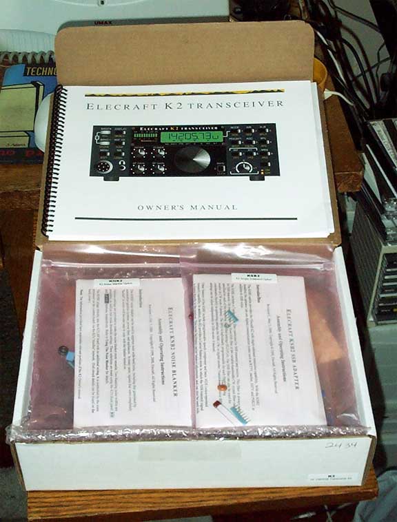
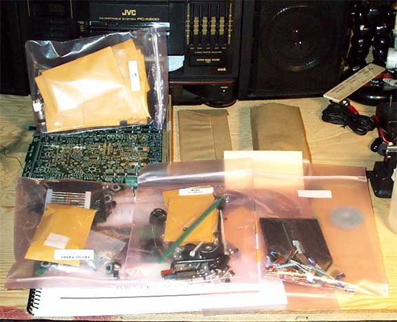
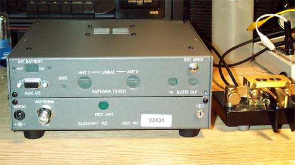
and her family.) The kit, S/N 2434, came on Christmas Eve. I inventoried the
parts in December and began building the rig in January. I worked anywhere
from 30 minutes to two hours on the kit, five or six nights a week. I
finished the base kit and made a contact on March 2, 2002. I estimate it took
about 60 hours including solving a big problem described below. The
SSB option took about 9 1/2 hours, and the noise blanker took about
3 hours. The two options were completed on April 7, 2002.
After that, I purchased an RS-232 control interface and
completed it in about 4 1/2 hours. I plan to purchase the 100-watt
option soon. Update: I completed my KPA
100 in September,
2002.
Well, I finally ordered the K2, the SSB option, and the noise blanker before
Christmas of 2001. (Actually, the options were Christmas gifts from my wife
and her family.) The kit, S/N 2434, came on Christmas Eve. I inventoried the
parts in December and began building the rig in January. I worked anywhere
from 30 minutes to two hours on the kit, five or six nights a week. I
finished the base kit and made a contact on March 2, 2002. I estimate it took
about 60 hours including solving a big problem described below. The
SSB option took about 9 1/2 hours, and the noise blanker took about
3 hours. The two options were completed on April 7, 2002.
After that, I purchased an RS-232 control interface and
completed it in about 4 1/2 hours. I plan to purchase the 100-watt
option soon. Update: I completed my KPA
100 in September,
2002.
The best things about the rig are
And, there are four peeves:
All and all, this is a great rig and a great kit. I'm glad I purchased the kit and that I built it myself.
Although, Elecraft says this is a intermediate kit, I'd call it advanced.
Elecraft support is great! They offer e-mail support, which is very good, and they have an excellent web site which includes PDF versions of the manuals for the rigs and options, modifications by Elecraft and others, and an e-mail reflector.
 The kit is very nicely done. It contains quality parts, great solder mask
boards, and clear instructions. (You can download the manuals from the Elecraft web
site before purchasing, if you want to see how clear the instructions
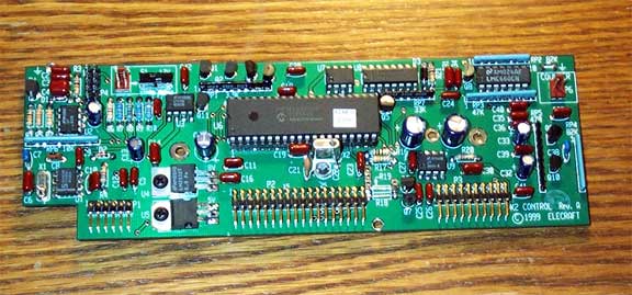
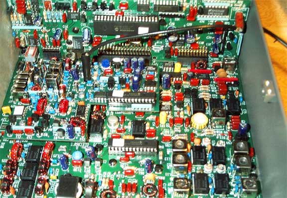
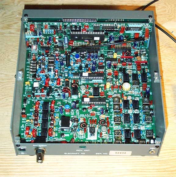
are.) The base unit is built around three PC boards: the RF board
that fills the bottom of the rig, the front panel board, and the
control board. The front panel and control boards plug into the
RF board.
The kit is very nicely done. It contains quality parts, great solder mask
boards, and clear instructions. (You can download the manuals from the Elecraft web
site before purchasing, if you want to see how clear the instructions
are.) The base unit is built around three PC boards: the RF board
that fills the bottom of the rig, the front panel board, and the
control board. The front panel and control boards plug into the
RF board.
One nice thing about the kit is that the resistors come on a tape in the order in which they are installed. I'm red-green color blind, so I really appreciate having the resistors pre-sorted. (The options I built don't have pre-sorted resistors, but there aren't enough resistors in the options for this to be a problem).
The base rig is constructed in three parts. After each phase, the partial kit is tested. For such a long kit, the feedback during this testing is helpful. In the first part, the two smaller boards are built and a few components are added to the RF board. Once this part is completed, the builder crosses his fingers and turns on the rig. If all is well, "ELECrAFt" is displayed on the large LCD display and the controls function to some degree. Part II takes the longest time. In this part, the the synthesizer, receiver, and filters for 40M are built. Once this part is complete, tests and some alignment tasks are performed. Finally, in Part III, the transmitter and the filters for the remaining bands are constructed. At the end of Part III, the rig is aligned. Alignment is fairly easy and straight forward. Many builders spend some extra time aligning the filters using an FFT application. (There are actually a few steps after Part III including installing the speaker.)
The kit is near perfect. The only real complaint is the description of the double-sided tape that is used to hold a bezel in place. The problem with the instructions is the tape isn't typical in that what you really have is some clear glue between two backings.
 Once the rig is built and aligned, then you can build options. I
built the SSB module first and then the noise blanker. I found the
SSB option to be more difficult than the base rig. One section
of the board has
closely spaced components, and the solder pads are more like solder
rings. I also found it hard to mount some of the capacitors close
to the board because of their lead spacing.
Once the rig is built and aligned, then you can build options. I
built the SSB module first and then the noise blanker. I found the
SSB option to be more difficult than the base rig. One section
of the board has
closely spaced components, and the solder pads are more like solder
rings. I also found it hard to mount some of the capacitors close
to the board because of their lead spacing.
I encountered a problem while installing the power switch.
I was holding the switch in place before soldering, and it appeared
to be flat on the board. But, after soldering, I noticed that the
switch was rotated a bit. I got some help from Mike, N4GU, who was
able to heat three pins of the switch and bend the switch in place.
The main problem I had was discovered at the end of Part II. The first step in the testing and alignment phase of Part II was to check the PLL reference oscillator frequency. The oscillator wasn't working.
I exchanged e-mail with Gary, AB7MY, at Elecraft about this problem and he gave me many good suggestions based on his experience troubleshooting K2's. He was very patient. I spent about a week thinking about and troubleshooting the problem. I cleaned up solder joints and tested connections, but the oscillator was still dead. I finally removed the capacitor connecting the reference oscillator to the next stage, and the oscillator started working. It didn't take me long after that to find a solder bridge on the component side of the board. It wasn't visible with a magnifier, but by eliminating other possibilities, I knew where the problem had to be. A little heat and solder-wick did the trick.
 Had I thought about it, I could have used an ohm meter to look for this
short at the input of the next stage. That would have saved me a lot
of time. It was smooth sailing after that problem until I got to the
options.
Had I thought about it, I could have used an ohm meter to look for this
short at the input of the next stage. That would have saved me a lot
of time. It was smooth sailing after that problem until I got to the
options.
I had four other soldering problems. The first three were "not soldering" problems. I think had I had a better magnifier, I wouldn't have missed these unsoldered pins. I did check the boards visually, but, had I been a bit more careful, I could have found these problems earlier. In any case, it only took a short time to trace these problems down.
Thanks to my wife Sue Ellen, KD4LQO, for her positive support while I
was building the kit.