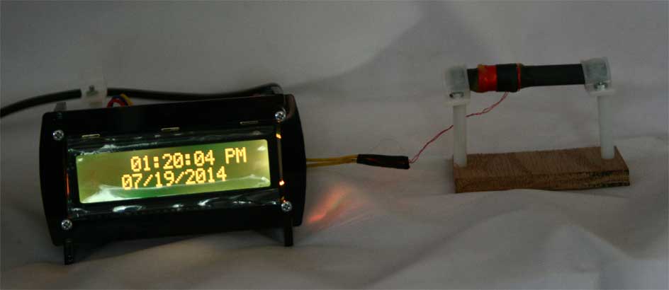
This article describes a prototype clock I built which has the following features:
For information about the WWVB receiver I used, the time format, and notes about interference, see Using the SYM-RFT-60 WWVB Receiver. The WWVB signal is not available at all times of day due to longwave propagation. The signal is also subject to various types of interference including signals from the clock components.
WWVB sends one data frame over the period of one minute with each bit taking one second. The WWVB legacy format decoded by the receiver contains no error detection bits, so the clock cannot easily tell if a given frame represents a valid date and time or a corrupted date and time. The clock software deals with this in three ways:
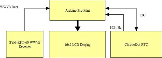
There are four major components of the clock (see the parts list below): an Arduino Pro Mini, a Maxum Integrated DS3231-based RTC, an LCD display, and a SYM-RFT-60 WWVB receiver module:
The clock is set to UTC by WWVB. The time can be displayed as UTC or some timezone offset from UTC. In normal display mode, one toggles between UTC and local time by pressing the 5-way switch up. Pressing the switch down toggles the debug display which shows the state of WWVB reception and the last time the clock was set by WWVB.
The code has several modes and options that are stored in EEPROM that is part of the CPU. The following options are settable
The motivation for "once a day" mode is to allow the operator to select the best time of day to try to set the clock from WWVB based on longwave propagation. This mode might be useful if the clock sets to invalid times if attempts are made when propagation is poor; however, I have not seen the clock set to an invalid time.
The clock software handles interrupts from the WWVB receiver and from the 1024 HZ square wave generated by the RTC. The latter is used to keep the time when the clock is powered. Other clocks with an RTC merely poll the time kept by the RTC rather than counting clock ticks. Both approaches will work; however, I felt that synchronization between the clock time and the WWVB time was easier running two interrupt handlers.
In normal mode (outside of the setup menus), the main routine polls the time for a change and the 5-way switch. Any time the time changes, the display is updated. Any time one of the switch contacts closes, the switch is debounced and the necessary action is taken.
When WWVB sets the clock, the main routine writes the updated time to the RTC. Because of the amount of processing when the time is set, the code delays 15 seconds before setting the RTC. This delay is the result of superstition on my part.
The software is written as a normal Arduino sketch with several additional classes. There is a DateTime class, a WWVB class, and several classes used for display of the menu items used to configure the clock. The Arduino library has a DateTime class; however, I created a custom DateTime class for the project.
Each time the 1024 Hz. clock ticks, the tick() method of the main DateTime object is called. Every 1024 ticks, the seconds counter is updated and the date and time are corrected in case of rollovers in the minutes, hours, day, month, or year fields. A pointer to the main DateTime object is given to the WWVB object. Whenever it detects the correct time, it sets the DateTime object. The main sketch polls the "changed" flag in the DateTime object to determine when the display is to be updated.
The WWVB object takes data from the WWVB receiver. It times pulses from the receiver and decides if the pulse represents a logic 0, a logic 1, a marker bit, or a pulse that is too short as the result of interference. The pulse width values for WWVB are given in the table below along with the values used by my software. The pulse widths are noticeably shorter as produced by the receiver and measured by the Arduino.
| Logic Value | WWVB Pulse Duration | Measured Pulse Width |
|---|---|---|
| 0 | 200 ms | 90 < pulse < 225 |
| 1 | 500 ms | 225 < pulse < 600 |
| Marker | 800 ms | pulse > 600 |
The menu system is primitive. In normal display mode, a scrollable list of submenus is displayed on the LCD display when the 5-way switch is pressed. The up and down positions of the switch are used to scroll through the list. Pressing the 5-way switch activates a submenu. The submenus use the up, down, right, and left positions of the switch to select and change values.
A small set of display widgets were created for common operations such as setting a time and setting an integer value such as time zone.
The software is currently not complete. The menu items to set the date and time manually are missing. Daylight Saving Time (DST) processing has not been developed, either. Although DST changes are indicated by bits in the WWVB frame, the receiver cannot always receive WWVB, so I plan to have the software change to DST at the proper time independent of WWVB. I also have to implement the ability to add a leap second when indicated by the WWVB time frame. Update: I completed these features (9/2014).
Developing software that deals with timezones can be tricky. The Problem with Time & Timezones - Computerphile is a funny and informative video about writing software to deal with clock software.
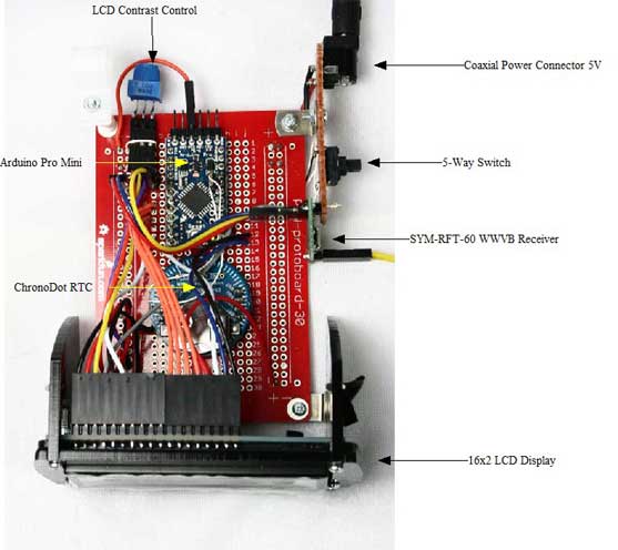
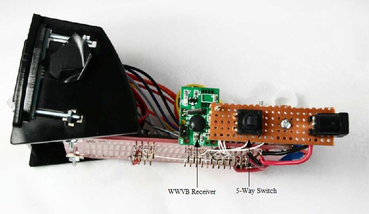
The original clock was constructed using a standard breadboard with spring clips. Once the basic system was working, I moved the Arduino, LCD display, and RTC to a PCB that has the same layout as a standard breadboard. This prototype version of the clock allows me to experiment with the placement of the WWVB receiver and antenna. The best solution to date has been to place the antenna several inches away from the PCB to avoid interference from the Arduino.
Some other clock builders have worked on shielding the WWVB receiver and/or antenna:
The last reference is part of a series that I found very helpful when I was getting started on this project.
Instead of using a standard Arduino board and RTC, the ICs from these boards could be used to make a custom clock. The Arduino Pro Mini uses an ATmega168 processor. The Arduino bootloader can be burned into a stock processor. The ChronoDot uses a Maxum Integrated DS3231. So a custom PCB could be designed to hold an ATmega168 and the DS3231 and additional components to create a neater looking and smaller clock.
I used most of the pins on the Arduino. There are two analog input pins, A6 and A7, that were not used. These pins are unlike other analog pins and cannot be used for outputs. The serial interface is still available, so the clock could provide time reports to a computer. The FTDI cable can still be connected to the Arduino to update the software.
I used connectors to make the connections between the main board and the WWVB receiver and LCD display. This arrangement provided the flexibility I needed to make changes to the hardware as the project evolved.
Articles on the WWVB propagation indicate that signal reception can be difficult during the summer months in some parts of the U.S. The signal is strongest at night, so some articles recommend that the best time for synchronization with WWVB is during nighttime hours for both the receiver and transmitter. However, I am fortunate that in my location in Virginia, my clock will synchronize with WWVB numerous times during the day even during the summer months.
The The Current Readability of the WWVB Time Code site gives WWVB readability for four sites in the U.S. Reviewing this site over time can help give you a feel for the reliability of WWVB signals.
The LED on the WWVB receiver board can be used to orient the antenna for a good signal. When reception is good, the LED will blink once a second for periods of 200 ms, 500 ms, and 800 ms. If the LED flickers faster than one pulse per second, there are two possible causes: poor reception and interference. In the former case, changing the antenna orientation or making another attempt at a different time might allow synchronization. In the later case, try moving the clock away from computers, microwave ovens, or other sources of interference.
Orienting the antenna takes some practice. The clock contains a debug mode which displays the state of WWVB reception and the last date and time that synchronization was attained.
Parts
After some experience with the clock, I found that configuring it to set after receiving two consistent WWVB frames leads to an invalid time or date being set occasionally, perhaps once a month or more. For this problem to occur, two frames in a row have to experience errors in the same bits.
So I'm currently running the clock in the mode that requires the clock to receive three consistent frames before setting the date and time. I have not seen any errors after going to this mode; however, the clock gets set from WWVB less often than in the two frame mode. Because of the accuracy of the real-time clock, the clock is still accurate.
Heuristics could be added to the code to ignore suspicious time settings that deviate from the current time and date if two-frame mode is required. (7/7/2017)
Sue Ellen, KD4LQO, and Mike, N4GU, listened to all the gory details as I worked on the clock. Sue Ellen gave me the WWVB receiver as a gift. Mike made some helpful suggestions about shielding and noted that he had a commercial clock with a detachable antenna. Ray, KE4TJC, forwarded me a pointer to the timezone video.
Mail questions or comments to me at benjy at tuxcat.com.