|
VS1053b Real-Time MIDI Mode |
The VS1053b DSP integrated circuit from VLSI Solutions is an MP3, Ogg Vorbis, AAC, WMA, FLAC, MIDI audio codec chip. The chip has a built-in polyphonic synthesizer which can be used in two ways: playing MIDI format 0 files and playing from a serial MIDI source like a music keyboard. The latter is referred to as real-time MIDI mode and is the focus of this page.
Although I purchased a VS1053b breakout board to build an MP3-playing alarm clock, I wanted to experiment with real-time MIDI mode since the idea of a cheap, polyphonic synthesizer is very appealing. With some limitations based on clock speed and the use of reverb, the chip can play up to 64 simultaneous notes with only 40 being sustained. I was not expecting the sound of a $1,000 synthesizer from the $19 DSP chip, but the instrument sounds are very nice for the price. See the datasheet for a list of instruments and percussion sounds available in the General MIDI banks.
This page is a brief tutorial on using the real-time MIDI mode in the VS1053b. I cover the stand-alone configuration in which no microcontroller is used and then discuss information on controlling the VS1053b with a microcontroller.
There are two versions of the real-time MIDI firmware: one is included in the chip and an improved version can be downloaded to the chip. This section covers using the firmware-based version.
Figure 1 shows a simplified wiring diagram for using the VS1053b ROM-based real-time MIDI mode.
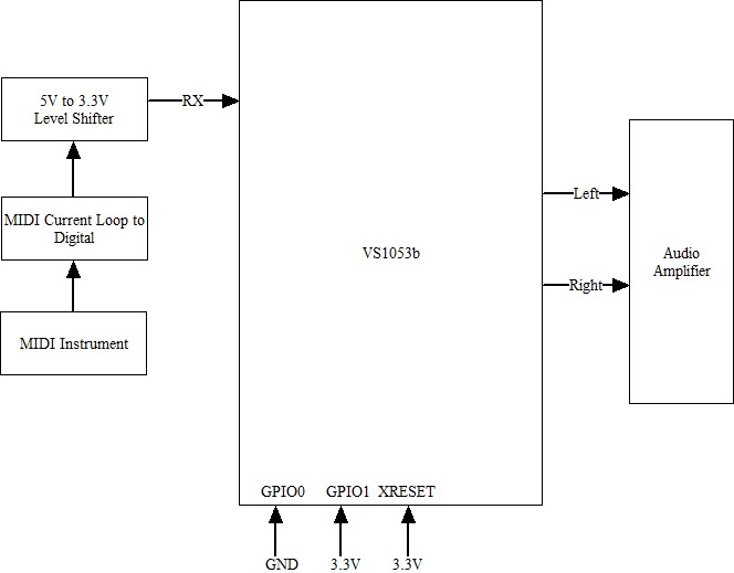
The "MIDI Current Loop to Digital" box is a common opto-isolator circuit like the one shown in Figure 1 in the VS10XX Real-Time MIDI Input paper. Some variations of the circuit connect pin 7 of the 6N138 through a 1K resistor to ground to improve switching speeds. If Vcc for the opto-isolator is 5 volts, a level-shifter to 3.3 volts is needed since the VS1053b is not 5 volts safe; however, the opto-isolator can be run from 3.3 volts, removing the requirement for the level-shifter.
If the GPIO0 pin is at logic 0 and the GPIO1 pin is at logic 1 when the chip is powered on or reset, then the ROM-based real-time MIDI mode is entered. MIDI commands sent to the VS1053b via the serial interface are played by the built-in General MIDI synthesizer. MIDI commands can be used to select the GM (General MIDI) bank and instrument.
Note that the XRESET line is an active-low reset. The schematic in the datasheet (and the breakout board I am using) have the XRESET line connected to a microcontroller output and a weak pull-down resistor to ground. If no connection is made to this pin, the pull-down resistor will put the chip into a power down state. In this state, the chip will not respond to MIDI commands. When using this chip with no microcontroller, the XRESET line should be pulled high. When using the chip with a microcontroller, the XRESET line can be tied to a microcontroller output so that the microcontroller can perform a VS1053b reset if required.
There are two limitations of the ROM-based real-time MIDI code that have been published by the vendor: First, the FIFO for the input UART is limited which might result in some MIDI messages being dropped at times of high activity. Second, the on-board MIDI code does not handle SysEx messages. In driving the chip with a YouRock guitar, I haven't noticed dropped notes due to FIFO overflow; however, driving the chip with a complex pattern from a sequencer or drum machine might reveal the problem.
MIDI SysEx messages begin with 0xF0 and end with 0xF7. The intervening bytes have specific meaning to specific brands of synthesizers, e.g., loading a patch, and should be ignored if the device does not support the specific SysEx message. But since the VS1053b does not understand SysEx messages, it treats the intervening bytes of a SysEx message as if they were MIDI commands. For example, if a 0x90 byte, a MIDI "note on" command, is included in the SysEx bytes, a note will be played.
There is a real-time MIDI application which can be loaded into the VS1053b that can be used to overcome these limitations. It has an extended FIFO buffer and ignores all the bytes of a SysEx message. This application is covered below.
The VS1053b can be controlled by a microcontroller using the SPI bus . There are two SPI chip select lines that distinguish between commands (Serial Command Interface - SCI) and data (Serial Data Interface - SDI) sent to the chip. If XDCS is low, then the chip interprets SPI inputs as data. If XCS is low, then the chip interprets inputs as commands. Commands are used to load plug-ins and applications into the chip and to control parameters like audio volume and reverb. In real-time MIDI mode, SDI, the data interface, provides an alternative means, in addition to using the serial RX line, to send MIDI commands to the chip.
Figure 2 shows the connections between an Arduino Pro Mini and the VS1053b. The figure is incomplete and leaves out important details. Not all connections are shown, e.g., the audio output lines. Also, the VS1053b is a 3.3 volt device. It can be used with a 3.3 volt Pro Mini directly or with a 5 volt Pro Mini with level-shifters between the two devices. In fact, I used a 5 volt Pro Mini and a VS1053 Breakout Board. The latter includes level shifters and a voltage regulator to make the VS1053b usable in a 5 volt system. It also includes an SD card slot for use when the VS1053b is used as an MP3 player.
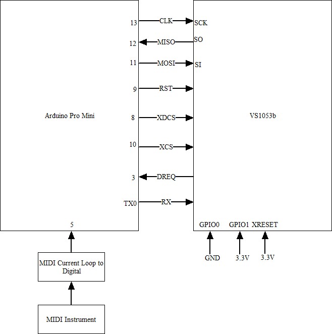
See the previous section for comments on the MIDI current loop input circuit.
The DREQ line goes low when the VS1053b is ready to accept data in Codec playing mode; however, it does not reflect the buffer state in real-time MIDI mode (according to a vendor forum post). The buffer state can be monitored by accessing the read and write pointers in the VS1053b as specified in this post. I have never experienced a buffer overrun in casual playing.
Note that the MIDI opto-isolator circuit is only necessary if you want to use a MIDI instrument to drive the DSP chip. The microcontroller could send a set of MIDI messages to the VS1053b from its memory without using the input device, e.g., the microcontroller could play a simple song during the initialization of a more complex system.
I initially attempted to use two Arduino SoftwareSerial interfaces concurrently with one receiving data from the MIDI device and one sending data to the VS1053b. Although the documentation for SoftwareSerial says that it is possible to have concurrent usage of serial ports as long as only one is receiving at a time, there are apparently other limitations. At the MIDI baud rate of 31250 bps, the sending interface would fail almost immediately. I had resisted using the hardware UART in the Pro Mini since it provides a handy debugging tool; however, the hardware UART is needed in my configuration.
With the SPI bus connected between the microcontroller and the DSP chip, there are two ways to send MIDI data: via the RX UART and via SPI. To send MIDI over SPI, each MIDI byte is sent using SDI with the first byte being 0x00. (Some documentation from the vendor indicates the value should be 0xFF; however, this is an error.)
There are two reasons for sending MIDI over SPI: First, if the SPI bus is needed for other reasons such as loading a plug-in, then a microcontroller pin can be saved by removing the connection to RX. Second, there is a way to monitor the input FIFO pointers via SPI that can be used to prevent FIFO overrun. I have not encountered lockups; however, it appears that it is possible to overrun the FIFO in SDI mode. This post discusses a way to do SPI flow control by reading the internal FIFO read and write pointers.
The vendor provides a number of plug-ins and applications for the VS1053b, but I will discuss only the two related to real-time MIDI mode. The vendor refers to code that can be downloaded to the VS1053b as plug-ins, applications, and patches. Each of these has different applications, but I will refer to plug-ins and applications interchangeably.
The first plug-in is used to start the ROM-based real-time MIDI mode without using the GPIO pins discussed above. There are some VS1053b breakout boards that do not provide a way to make connections to these pins, so the plug-in provides a means to start the real-time MIDI mode without modifying the breakout board. See VS1053b Real-time MIDI Start code on this page and the section on loading plug-ins below.
The second plugin is a replacement for the built-in real-time MIDI code called VS1003b/VS1033c/VS1053b Real-Time MIDI Input Application. This code extends the input FIFO buffer and ignores SysEx messages in their entirety.
Although the VS1053b can be configured to load from an external SPI serial EEPROM, this discussion relates to loading plug-ins from a microcontroller. The vendor supplies C language code sketches for loading plug-ins. Several plug-in formats are available, but I suggest using the .plg files which contain the plug-in array and template C code for loading a plug-in.
The current version of the plug-ins are in compressed form. A plug-in entry starts with a 16-bit address. The second 16-bit word gives a count of n. If the high-order bit of n is zero, then the next n 16-bit words are written to the given address. If n has the high bit set, the next 16-bit word is written n times (with n being considered as an unsigned 15-bit integer) to the given address. Words are written using the XCS (SCI) chip select.
Typically, the address value is either 6 or 7. Register 7 is the address in RAM to be read or written, i.e., it is the RAM address register. Register 6 is the value to be written to or read from RAM. An SCI read command reads from RAM while an SCI write command writes to RAM. The RAM address is auto-incremented after each read or write operation.
I had two problems writing plug-ins to the VS1053b. First, the real-time MIDI application is larger than the RAM on a Pro Mini. Second, some plug-ins are designed to start automatically while others require setting the start address. The real-time MIDI application is missing the code that starts it.
The solution to storing large plug-ins using an Arduino with an AVR processor is to use PROGMEM support which allows large arrays to be extracted directly from program flash memory instead of copying the large arrays to RAM first. The plug-in array is declared as a global variable with the PROGMEM modifier. Then, instead of accessing the ith plug-in word using
addr = plugin[i++] ;the following code is used:
addr = pgm_read_word(plugin+i++) ;
The declaration of the plug-in should have the PROGMEM modifier before the "=" as follows:
const unsigned short plugin[] = { /* Compressed plugin */
becomes
const unsigned short plugin[] PROGMEM = { /* Compressed plugin */
When I loaded the real-time MIDI application, it did not function, i.e., no synth sounds were produced. The problem is that the plug-in does not include the start address of the application which has to be written to the AIADDR address (0xa). I added 0x000a, 0x0001, 0x0050 (address, n, value) to the real-time MIDI plug-in to tell the DSP to start the application at RAM address 0x0050. An alternative would be to use direct SCI to write 0x0050 to address 0x000a.
There are a number of VS1053b libraries on the Internet which are helpful in understanding real-time MIDI mode. For example, MP3_Shield_RealtimeMIDI.ino contains a complete example of using real-time MIDI mode using the Sparkfun VS1053b shield. The example illustrates how to load a plug-in and how to send MIDI commands using both the serial line and the SPI bus.
This library waits on the DREQ line to be high before sending data to the VS1053b; however, it appears that the DREQ is not used for data synchronization in real-time MIDI mode.
Adafruit's tutorial for their VS1053b breakout board is primarily directed at using the VS1053b as a music Codec player; however, MIDI mode is covered under the MIDI Connections page. The API for the Adafruit VS1053b library is covered on the Library Reference page, and the library can be downloaded from the Downloads and Links page. There is a MIDI example that comes with the library, and the library has support for real-time MIDI mode. Plug-in support is different from what I outlined above as plug-ins are read from an SD card in binary format (.bin). Bin files are one of the plug-in formats available from the vendor.
This page gives a brief overview of MIDI messages. The offset for the channel and instrument is 0 but referred externally with offset 1.
I suggest putting the large real-time MIDI plug-in in a separate header file to reduce clutter in the main code.
From the examples I've seen, the VS1053b volume and the MIDI channel volume need to be set. The VS1053b volume value is a loudness attenuation for the left and right channels packed into a 16-bit word. 0x0000 is maximum loudness. The value is set by writing it, via SCI, into register 0x0B. The MIDI volume for channel one is set by sending the MIDI command 0xB0, 0x07, n where n is a volume value from 0 to 127.
Instrument selection is performed by sending MIDI commands to the VS1053b. 0xB0, 0x00, n selects bank n for MIDI channel 1. A MIDI program change command is sent to select a particular patch (sound): 0xC0, n selects patch n on channel 1. For example,
  0xB0, 0x00, 0x00
  0xC0, 24
selects General MIDI bank 1 (offset 0) in the VS1053b and selects the nylon string guitar patch (number 25 specified by 24 offset 0).
Note that in the MIDI messages shown above, the channel number is the low-order nibble of the first byte. In the examples, this value is 0 indicating channel 1. 0xC1, 24, for example, would select patch 25 on channel 2.
Reverb is on by default in real-time MIDI mode. It can be configured through the low-order four bits of the VS1053b config1 register at memory location 0x1e03. Looking at the following code, the RAM address of the configuration word is put in the RAM address register (register 0x07 - SCI_WRAMADDR). The word is read from the RAM data register (register 0x06 - SCI_WRAM) and the reverb bits (0-3) are set to 1 (reverb off). A zero value for these bits is auto mode which turns on reverb for certain clock rates. Values 2-15 are a room size (delay) parameter for reverb. Once the value is set, it is written back into location 0x1e03.
    uint16_t t;
    writeReg(SCI_WRAMADDR, 0x1e03); // Register Parametric.config1 address
    t = readReg(SCI_WRAM); // Read config1
    t = (t & ~0xf) | 1;    // Set reverb to 1 = off
    writeReg(SCI_WRAMADDR, 0x1e03);
    writeReg(SCI_WRAM, t); // Write the new value for config1.
I really like the VS1053b DSP. It works well as an MP3 player and an inexpensive synthesizer. Real-time MIDI mode, along with a microcontroller, could be used to build a simple MIDI recorder that could be used to capture musical ideas and play them back.
Page by Benjy Cline benjy at tuxcat.com.