The BenjyMometer - A DIY Wireless Thermometer System |
My primary interest in building this system was to get an accurate outdoor temperature especially on wet winter mornings in trying to determine if black ice would be a problem on the drive to work. I had two wireless thermometers and a remote reading mercury thermometer, and all three displayed different temperatures, several degrees apart.
Buildings, pavement, trees, and other objects that can store and radiate heat affect outdoor thermometers and also prevent proper sensor ventilation. Standards for air temperature measurements indicate that if a nearby object is x feet tall, the sensor should be at least 4x feet from the object. It should be five feet above the ground and be shielded from direct sunlight. Radiation shields/ Stevenson screens can be used to shield the sensor from rain and the effects of sunlight. This guide gives specifics on placement.
The problem with many department store wireless thermometers is the limited range. A unit advertised as "up to 75 feet" might only be good for 20 feet if the signal has to pass through a exterior wall. Because of this limitation, it is difficult to place the sensor far enough away from a house, trees, or other objects. This problem is the motivating factor for my building the BenjyMometer (portmanteau of "Benjy" and "Thermometer").
I began by experimenting with 315 MHz RF Link radios that I purchased from Sparkfun (see parts list section). These units use Amplitude-Shift Keying (ASK) and have an estimated range of 500 feet in the clear running at 4800 baud. My casual testing showed that the range outside was greater than 200 feet and over 100 feet through an exterior wall. (I did not test greater distances.) The transmitter can run at up to 12 volts, but I choose 6 volts as a compromise. I also decided to run the units at 1200 baud to improve reliability.
ASK is sensitive to noise and issues with clock synchronization between the send and receiver, so I used the VirtualWire library for the Arduino. The library includes error detection and a protocol that mitigates sender/receiver clock differences.
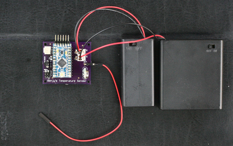
Remote sensors use battery power. In the case of outdoor sensors, the batteries must be reliable even during the cold of winter. Battery life is also critical since the electronics of my unit are in a watertight box with screw fasteners, making frequent battery replacement inconvenient. The final design used a 3.3 volt Arduino Pro Mini with a 3 volt AA battery power supply and a 6 volt AA battery supply for the transmitter. The Arduino is put into deep sleep mode except when measuring the temperature and transmitting it. The transmitter draws little current when not transmitting, so no mechanism is needed to turn off the transmitter.
To save battery power, the unit only reads and transmits the temperature every two minutes. A longer period would extend battery life, but battery life is typically more than six months. Each sending unit has an extra delay of several seconds based on its unit number. This allows multiple units to transmit on the same frequency. If transmissions from multiple units collide, the variable delay based on the unit number insures that they will eventually be able to send a temperature message in the clear.
The units also report their battery voltages to the receiving units so that the user can monitor battery status.
The final design goal of displaying temperatures on the web was implemented but is not currently in use by me. I find it easier to glance at a temperature display than to navigate to a web page or run an app.
I experimented with putting the temperature on the web with an ESP8266. While this approach worked, I didn't want to invest the time in writing a minimal C web server that would format the temperature display. I then tried running Lua on the ESP8266 but abandoned the effort when the code was in beta mode due to some stability concerns.
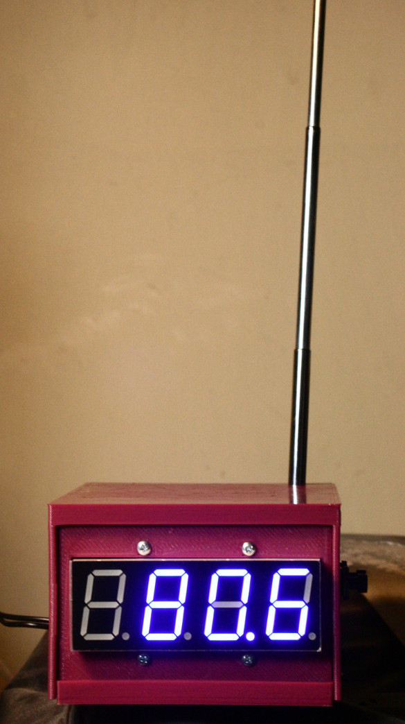
The final version of the BenjyMometer receiver provides a 3 volt logic serial port that outputs the temperature and sensor battery information. I wrote a Java program for the BeagleBone Black that parses this information and displays it in a formatted table on the web. But after using the system, I found I liked glancing at a large 7-segment display rather than using the web to access the outdoor temperature.
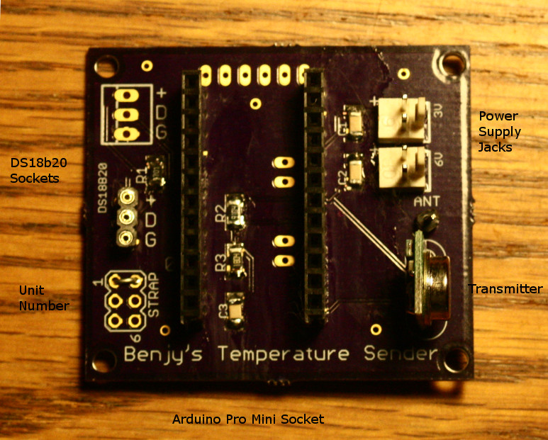
The temperature sending units use the following parts:
|
 |
As described in the design goals section, the Arduino code reads and reports the temperature every two minutes. It reports the battery voltages twice a day. When not performing these tasks, it is put in a deep sleep mode to conserve battery power. The AVR ATMega328, the Pro Mini processor, can only sleep 8 seconds before waking up. The processor wakes every 8 seconds, checks to see if the two-minute sleep period has expired, and goes back to sleep if more sleep time is required.
The system uses the Low-Power library for the Arduino to enter sleep mode. See this page for details after running the Pro Mini in low-power mode. Note that the current version of the Pro Mini has a jumper to disable the on-board regulator and power LED to reduce power consumption. The jumper points are connected with solder which I removed to turn off the LED and regulator.
To measure and report the 3 volt power supply that powers the Arduino is straight forward. The ATMega328 has a bandgap reference against which Vcc can be measured. The technique is explained on this page.
Measuring the 6 volt supply is more difficult. First, a resistor divider is used to drop the voltage to below 3 volts so it can be measured by the 3 volt Pro Mini. Normally, a low impedance divider is required to charge the analog-to-digital converter's sample and hold capacitor; however, such a divider will drain the battery faster. This page offers a solution by bypassing the high-impedance resistor network with a capacitor to allow the sample-and-hold to charge. I am not sure the value reported by the analog-to-digital converter in this setup is accurate; however, as long as the value reported can be mapped to a low battery, the setup is adequate. I'm still collecting data on the reported battery voltages.
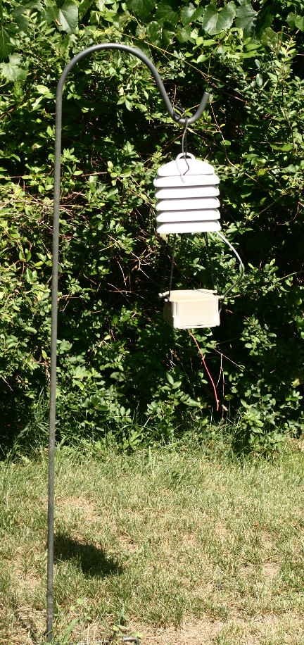
For the outdoor unit, I made a poor man's Stevenson Screen using some PVC pipe. Unfortunately, the unit does not prevent some solar heating in direct sunlight. The electronics hang under the shield with a cable going to the DS18b20 temperature sensor. I followed this video to make a watertight probe using the sensor.
The first two images below show the indoor sensor in a 3D printed case (a prototype version). The image on the right is my poor-man's radiation shield made from PVC pipe and a water tight electrical box. Notice its similarity to Nomad.
 Indoor sender |
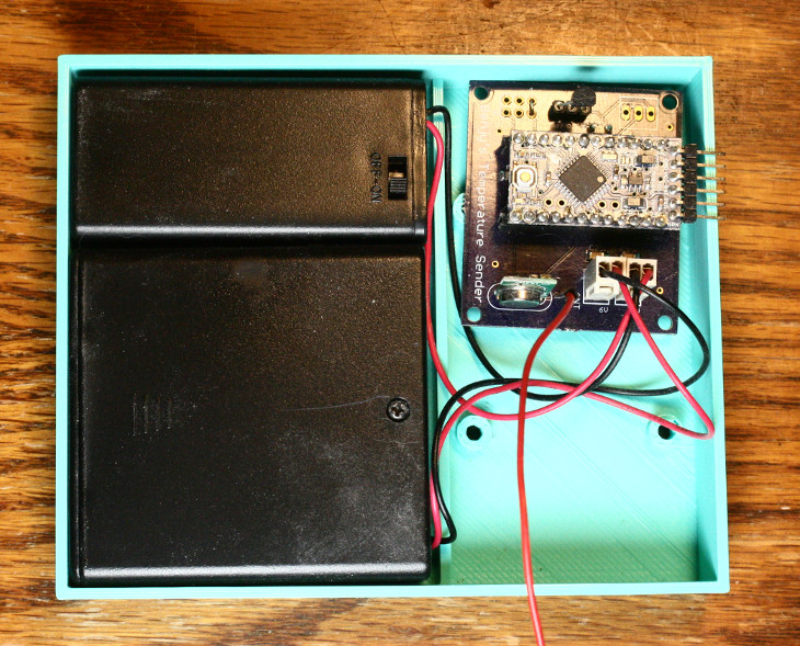 Indoor sender without top |
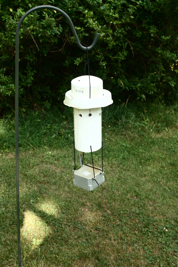 Poor man's shield |
On July 1, 2018, I replaced the poor man's shield with an AcuRite 06054M sun shield. The shield is meant to be used with a commercial wireless temperature sensor that pushes into the shield. Modifying the shield for the BenjyMometer sensor was easy because the shield snaps apart and back together, giving me easy access to the internal part of the shield.
At first I thought the new shield was working better than my homemade shield, but that seems to be a misunderstanding on my part. I plan to take more data and update the page.
The receiving unit is configurable for several display and reporting options:
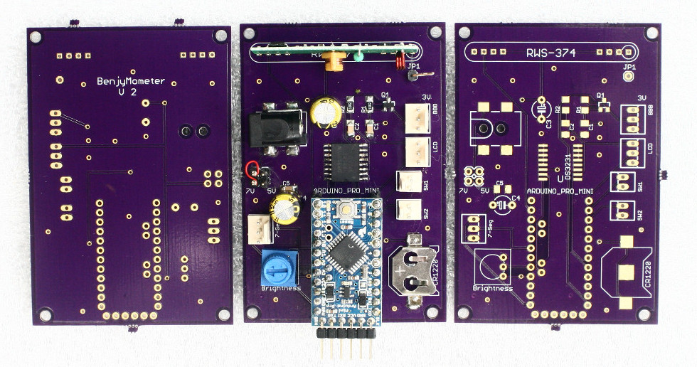
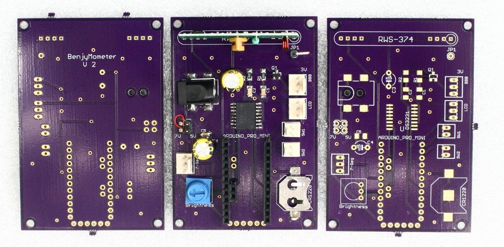
See the PCB without the Arduino installed.
If the unit is configured for a 7-segment display, two switches can be connected to the circuit board to control the display. One button switches between the different sensor units. The temperature is displayed for the selected sensor until another button press occurs. The second button causes the battery voltages and high and low temperatures for the selected sensor, along with the times the high and low temperatures occurred, to be displayed briefly. If the unit uses an LCD display, the temperature and battery voltages for two sensors are displayed.
One problem with the receiver is that 7-segment display boards typically generate a lot of noise on their power lines which interferes with the 315 MHz. receiver. The noise is generated as the digits are swept to display each digit. Rather than powering the 7-segment display and an Arduino from a single regulated power supply, a 7 volt unregulated supply is used which is connected to the on-board regulators on the display and the Arduino. This arrangement improves the performance of the system along with filter capacitors and ferrite beads. But the receiver performance is reduced a bit over a receiver using only an LCD display. When using a 7-segment display, the 315 MHz. receiver is powered from the Arduino Pro Mini regulator. When using an LCD display, the board can be configured to be powered from a regulated 5 volt supply.
The parts for a receiver are
The Arduino code waits for messages from the sensors, parses them, and updates its tables of current values. It also checks for missing messages from the sensors and indicates if a sensor reading is not up to date. The system records the high and low temperatures for each sensor with a time stamp read from the real-time clock. It also monitors switches that can be used to change the display or set the clock. To set the clock, the brightness potentiometer is used to select individual hour and minute values.
Each time a temperature or battery value message is received, the Arduino also sends the message to an optional BeagleBone Black which parses the messages and formats a web page with current temperature and battery values.
There were two problem during the implementation phase of the receiver. First, I used a DS3231 layout for the RTC that I found on the web; however, the layout was for an SO-16 IC, not an SO-16W (wide) that matches the chip. So a new PCB was fabricated. Second, the RTC can generate a square wave with a precise period. I do not use this feature, but I made a connection on the PCB from the square wave pin to the Arduino for future use. I found that if I enabled the square wave during start up, the RTC would forget the time although it was backed up by a watch battery. I had not enabled the pull-up resistor in the Arduino for this pin, so the oscillator line was floating and being capacitively coupled to the RTC reset line. Enabling the pull-up or turning off the oscillator remedies the problem.
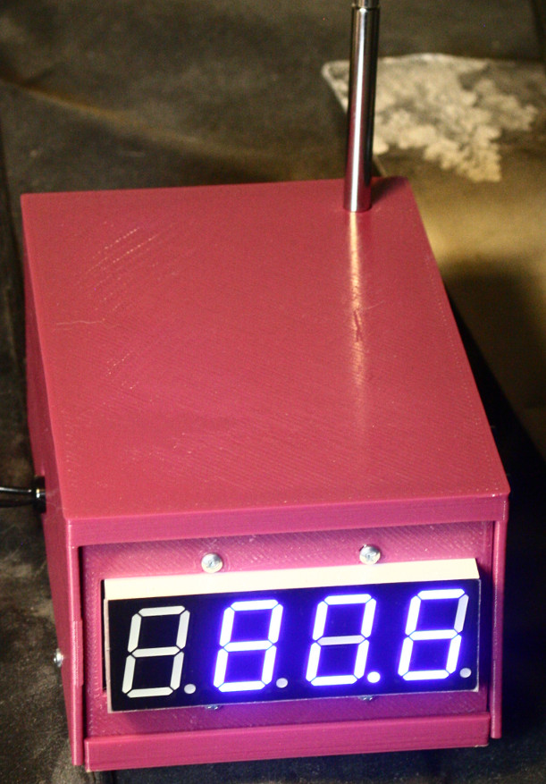
Receiver in 3D printed
case
This project seemed to drag on as I experimented with different temperature probes and the 315 MHz. radios. I also experimented with the ESP3822 and wrote code for the BeagleBone Black for the web display of temperature. Additional time was required to produce custom printed circuit boards and 3D cases. Time was used to resolve the interference issue with the 7-segment display and the 315 MHz. receiver. During much of the experimentation time, I used prototype versions of the system and began to rely on it.
I need to do more work on the outdoor radiation shield or purchase a Stevenson Screen. Due to the many tall trees near my house, probe placement is problematic, so additional experimentation is needed.
I am pleased with the electronics and meeting my design goals. I'm less pleased with the radiation shield.
Given the time and materials costs, the purchase of a commercial weather station would have been easier. However, I enjoyed designing and building the BenjyMometer and customizing it with features I wanted.
I build an improved receiver using an ESP32.
As with many of my projects, my wife Sue Ellen was supportive throughout the process as was Mike Barts. Thanks to both for the encouragement and suggestions.