


|
|
|
|
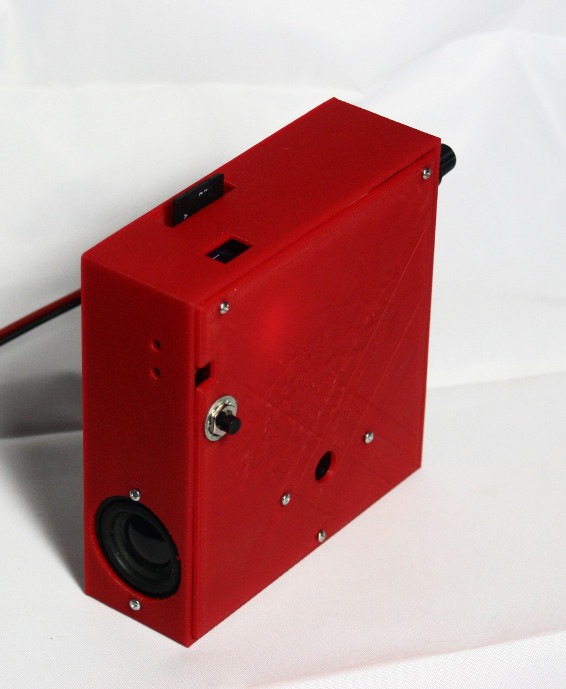
The Alarming Clock is a DIY alarm clock and MP3 player. I built it for my wife who wanted different alarm times for different days of the week. The clock has a TFT touch screen that displays the time and allows the user to play MP3 files from an SDCard and set and edit alarms. These functions can also be performed with a web browser on the local network.
The question is why build something whose function could be replaced with an app on a smart phone. The use of a dedicated clock over a phone is a matter of personal preference.
|
| |||||||||||||||||||||||||||||
| Hardware | Late beta. PCB has known errors with workarounds |
| Software | Beta. Testing is in progress. |
| 3D Printed Case | Beta. Needs a way to secure speakers and buzzer |

The Alarming Clock is built around the ESP32 dual core processor with Bluetooth and WiFi. See the history section for information about design choices.
When the clock is idle, it displays the time of day in either 12 or 24 hour format. From the time display, the user can select "Menu" for setting alarms and changing settings or "Play" to play songs. Each of the 7 alarms can be enabled or disabled and can either sound the buzzer or play a song at the alarm time. During power failures, songs are not played, and the buzzer is sounded regardless of the alarm setting. The user can select a single song to play at the alarm time or select a directory indicating all the songs in the directory are to be played. In other words, play lists are implemented as directories.
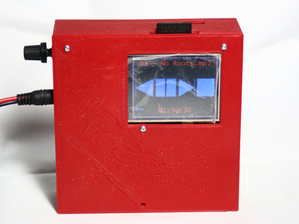
If the user selects "Play" from the time screen, the top-level directory on the SDCard is shown. The user selects a song to play by touching it. For directories, the user can touch the lefthand side to play all the songs in the directory or the center of the directory to open it for exploration. When a song is playing, player controls are displayed that allow the user to select the previous or next song or to pause or stop play.
When a song is played during an alarm, the audio volume begins low and ramps up to the current volume control setting to make the transition from sleeping to waking easier.
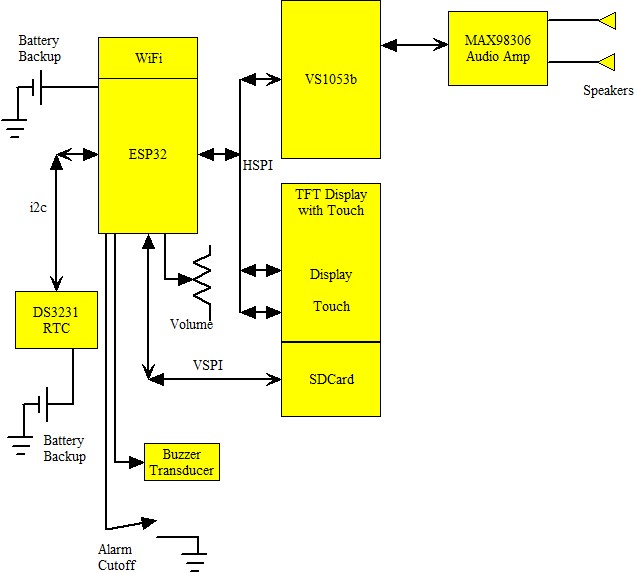
The diagram gives an overview of the system architecture. The VS1053b MP3 player, the TFT display, and the display touch controller all share an SPI bus, which is called HSPI for the ESP32. The SDCard requires a dedicated SPI bus and uses the VSPI bus. The DS3231 real-time clock (RTC) communicates with the ESP32 using an I2C bus.
The MP3 breakout board drives an optional MAX98306 class D audio amplifier that drives 40mm speakers. Using a stereo connector, the output of the MP3 board can be connected to an external amplifier or headphones.
The system is powered from a 5 volt source; however, the ESP32 runs from a 3 volt battery during a power mains failure. The goal is to power the ESP32 long enough so that it can sound a morning alarm if the power fails during night time. The RTC also has a battery backup for longer power failures.
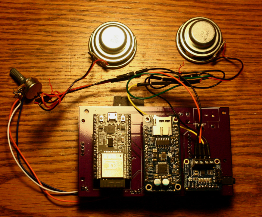
The ESP32, VS1053b, and MAX98306 are contained on breakout boards which plug into a custom printed circuit board. A DS3231 is soldered to the custom PCB.
Software for the system consists of a number of tasks.
FreeRTOS queues and shared variables are used for intertask communications. The main task initiates the playing of an MP3 file by setting the file to play in a shared variable and then sending a queue message to the player task. The player task opens the file and sends 32-byte blocks of it to the VS1053b. When the player task is finished playing a song, it sends a queue message back to the main task.
There is an interrupt handler in the watcher task that monitor a GPIO pin connected to a voltage divider. This pin is normally at logic one but falls to logic zero during a power failure. The interrupt handler detects the power failure and queues a message to the watcher task. The watcher task wakes up and puts the ESP32 into light sleep mode to conserve battery power. The processor remains asleep until either power is restored or the RTC signals that the first alarm has triggered. In the latter case, the processor produces a buzzer sound until the user presses the alarm switch or the battery is exhausted.
The volume control is connected to an ADC (analog-to-digital converter) on the ESP32. This is a linear potentiometer. To give a wider range of volumes, the pot value is modified with a natural log function in software. The processor also monitors a switch conntected to a GPIO pin which is used to end a buzzer alarm.
 |
 |
The ESP32 is supported by two toolchains: Arduino and a version of FreeRTOS. The former is implemented on top of the latter, and FreeRTOS calls can be made from an Arduino application. I chose to use the FreeRTOS (ESP-IDF or IoT Development Framework).
The ESP32 IDF includes an SPI driver. The driver seemed incomplete when I first started the project, and the documentation wasn't clear to me. I had to empirically determine the delay between sending a command to a device and when the data was available.
I originally used
Because the IDF requires a dedicated SPI bus for the SDCard, I could not use
the SDCard slot on the VS1053b breakout board since the MP3 player and the
SDCard slot were connected to the same SPI pins. So I used the SDCard slot on
the TFT card. SDCards in the TFT SDCard slot would only support very slow
read rates which were too slow to play music. The problem is that the TFT card
used "poor man's level shifters", i.e., resistors, to allow a 5 volt device to
talk to the SDCard. The resistors introduced an RC delay, thus reducing
the maximum transfer speed. I replaced the resistors with jumpers.
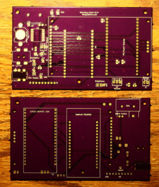
I had a custom PCB fabricated. When I plugged it into 5 volts, nothing
happened. It turned out the power connector was reversed. Fortunately,
the Low Dropout Regulators (LDO) on the ESP32 and VS1053b handled the
power reversal without an damage. Since the TFT board is powered from
the VS1053b LDO, it was not damaged. I had not installed the RTC.
After I reversed power to the PCB, the system worked; however, MP3 files
would only play at reduced speed. I thought the problem was related to
the power reversal, but it was not. I had made a software change right
before I had the PCB board fabricated that I had not tested. Before playing a song,
I reset the VS1053b. This software reset resets the clock divider on the
MP3 board which results in MP3's being played slowly.
Since the ESP32 has support for I2S, I considered using that feature instead
of an MP3 player board. I did some experiments, but I abandoned using I2S
because of the large size of the library to decode MP3.
I originally planned to use an NE555 oscillator to drive a transducer for
the alarm buzzer. The buzzer sounds under two conditions:
There was a problem with the display touch controller. With one ESP32, the
touch controller would fail to initialize about once in fifty processor
reboots. To allow the touch controller to signal a touch by pulling a
line (INT) low, the controller has to be put into low power mode by sending
a command to read a register with the low bit cleared. With a second ESP32, the
touch controller would never bring the INT line low. I used a logic analyer
to determine the problem. During an SPI transfer, the receiver and transmitter
are both active. After a command is sent to the touch controller, data is
send back to the processor. During this time, the touch controller receives
whatever data is on the processor transmission bus. I had assumed that
the SPI API call I had made would send zeros during the time data was being
received from the touch controller. This was not the case and random data
was sent to the controller chip. If the data ended in a zero bit, the touch
controller was put into low power mode and worked as expected. Otherwise,
the bit indicated that low power mode was not to be entered. I added data
to the transmission that was padding zero bytes.
I noticed that the speakers became hot when the unit was powered on even when
there was no audio playing. The problem was a defective Adafruit audio
amp. Replacing the amp fixed the problem.
With the 555 buzzer, I designed a logic circuit that would sound the alarm
under these two conditions. This design added a quad NOR gate package, a
D-flip-flop, and the
NE555, so I abandoned it for a simpler solution where the ESP32 creates the
alarm sound using a DAC. During a power failure, the ESP32 enters sleep
mode. If the DS3231 triggers an alarm before power is restored, the ESP32
wakes up and sounds the alarm. During power failures, the ESP32 runs off
a battery.
benjy at tuxcat.com